As an artist, I occasionally produce works of art without first deciding what I want to draw or paint; instead, I simply want to add colours and lines to the drawing or canvas without considering the final product. Let’s follow our own instincts and unconscious directions!
Then I considered, “What if I am using electronic components, a soldering iron, and similar tools as my materials instead of paintbrushes and pens, to create a project without prior planning, and not to worry about the outcome that the project, no sketch of how it would look like, and do not care whether it would be successful or fail?”
The schematic below uses FTDI to upload the design and connects the LED to pin D13.

Step 1: Parts & Tools
Parts Required
- ATmega168/328 preloaded with Arduino Bootloader,
- 16 Mhz Resonator,
- 10K Resistor (Radio Shack #271-1335)
- 0.1uF Capacitors (Radio Shack #272-135)
- 3mm red LED(Radio Shack #276-026)
- 1K Resistor (Radio Shack #271-1321)
- 6-pin Male Header (as the connector to FTDI cable to upload the sketch)
This is the minimum components to get Arduino up and running.
Tools
- Solder iron and Solder station
- Hookup Wire
- Diagonal Cutter
- Pliers
- X-Acto Knife
- Wire Stripper
- SolderSucker
Step 2: Power Supplies


I removed an ATMega168-20PU from an old Arduino board. The board still works, therefore use the old ATmega168 chip instead of the newer ATmega328P.
First, I considered the Microcontroller’s power supply. The 5V regulator was first.
Next, 3.3V regulator. Soldering without a PCB.
5V and 3.3V Power Supplies
Here are the part lists of the 5V and 3.3V regulators:
- 0.1uF Capacitors (Radio Shack #272-135)
- 100uF Capacitor (Radio Shack #272-1025)
- 10uF Capacitor
- +5V Voltage Regulator (Radio Shack #276-1770) or (DigiKey #LM78L05CZFS-ND)
- +3V3 Voltage Regulator (DigiKey #MCP1700-3302E/TO-ND)
- Diode 1N4001 (Radio Shack #276-1101)
Step 3: Antistatic Tube As a Case?


- I started drawing lines on the tube itself. I assumed my older power supply were roughly the same size as the tube.
- I also placed the ATMega168 microcontroller linear to the power supplies.
- I chopped the tube’s top to fit the power supply and microcontroller.
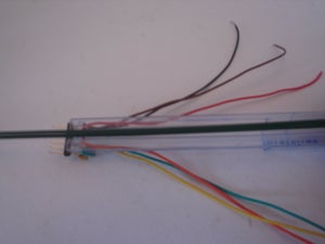
- I installed the FTDI connector (6-pin male header) at the tube’s end.
- I notch the tube’s end. (last 3 pictures)
Step 4: How I’m Going to Upload the Sketch?


Continue on from the step 3, I prepared an FTDI connector using a 0.1uF capacitor, 6-pin male connector, and leftover hookup wire.
Step 5: What Is the Energy Source?


- The ATMega168-20PU datasheet said the microcontroller could use 3.3V to 5V.
- I wonder whether I could utilise a 12V automobile remote battery.
- The 5V Voltage Regulator IC- LM7805 can withstand 30V, thus it’s fine.
- So, I used a 12V Type 23A size ‘N’ Alkaline Battery (Radio Shack #23-144B) and Holder.
- I installed the battery holder near where I’d put the microcontroller.
- The images below show how I installed the battery holder.
Step 6: Eyes & Brain


following a closer examination of what had been done up until this point. The FTDI connector and the portion of the tube before it was cut out both seem quite organic to me; they resemble an animal’s head and mouth, respectively.
In order to make it more resemble animal eyes, I decided to add two LEDs that would be attached to pin D13 of the ATMega168.
Another thought struck me when I realized that 6 + 8 = 14, which also matched the number of pins on each side of the microcontroller. I ought to have used two 6-pin and two 8-pin long contact leg female headers so I could reprogramme the ATMega168 and use it for any project.
I finally decide to attach the female connectors to the battery holder and arrange them down the side after some trial and error with the microcontroller in place, etc. I began soldering those female connectors’ legs to the pins of the microcontroller.
Step 7: Is It Alive?


I then connected pins D9, D10, and Ground to the 16 MHz resonators. and connected the ATMega168’s D7 and D8 with 0.1uF pins.
Now that I have a Freeform Arduino, it’s a good idea to try it out to make sure it works properly and is alive.
To verify that everything was functioning, I loaded the “Blink.ino” example from the Arduino IDE.
Step 8: Add Arms and Legs


I decided it would be a good idea to finish the project by adding the arms and legs to it as the “Freeform” design began to resemble an animal.
But is the material appropriate for it? Upon a second inspection of the toolbox and component case. These 16 gauge and 18 gauge stem wires, which my wife purchased from an arts and crafts store and had leftovers from a project involving imitation flowers, were what I found.
Due to the green color of 16 Gauge, I initially chose it, but later I changed my mind.
I used masking tape and a very small amount of super glue to join two of the stem wires.
The stems were then bent into the shape of arms and legs.
Note: the pictures below were reproduced to show I did it. I did not take the pictures while I worked on them.
Step 9: Adds a Motor Skill?


At this point, I thought, This is the animal that already has a brain and power, but it has nothing to make it moves like the animal.
The idea came up, How about making it dance, just adding the vibrating motor to the beast?
I, therefore, added a little motor, similar to the pager’s tiny vibrating motor.
The schematic that I drew out when the idea first occurred to me is shown below.
The listings of the components I utilized are as follows:
- BC337 (DigiKey #BC33740TACT-ND) or you could use TIP120 NPN Transistor (Radio Shack #276-2068) , but I found that this component is kind of too big for the project.
- 1K Resistor (Radio Shack #271-1321)
- Diode 1N4001 (Radio Shack #276-1101)
- Pager Vibrate Motor (Radio Shack #273-107)
After testing the motor, I realized that the motor pulled a lot of voltage, I decided to add an extra battery, CR1220, and Battery Holder (Radio Shack #270-0008). Later I learned that it a discontinued item,
Step 10: IR Receiver


There is now a new issue! How might I manage the motor?
That’s it! IR Receiver I decided.
And here is the components I bought for this project.
- IR Receiver at 38 kHz (Radio Shack #276-0143)
- IR LED (Radio Shack #276-640) – Purchased for testing purposes only; not used in the project.
- I matched the IR Receiver with the Polaroid Remote. (To learn how to do this, go to Ken Shirriff’s site.)
Sketch

I utilized Ken Shirriff’s IR Library and modified IRrecDemo.ino, one of the library’s sample sketches.
In order to acquire the value of the Enter button so, I can use it to switch on the motor, I also use another example, IRsendDemo.into, to decode my Polaroid IR remote. (Ken’s blog at the above-mentioned site has detailed instructions on how to achieve this.)
/* * IRremote: IRrecvDemo – demonstrates receiving IR codes with IRrecv * An IR detector/demodulator must be connected to the input RECV_PIN. * Version 0.1 July, 2009 * Copyright 2009 Ken Shirriff * http://arcfn.com */ #include <IRremote.h> #define motorPin 12 #define ledPin 13 int RECV_PIN = 9; IRrecv irrecv(RECV_PIN); decode_results results; void setup() { Serial.begin(9600); pinMode(ledPin, OUTPUT); digitalWrite(ledPin, LOW); pinMode(motorPin, OUTPUT); digitalWrite(motorPin, LOW); irrecv.enableIRIn(); // Start the receiver } void dance() { delay(200); digitalWrite(motorPin, HIGH); digitalWrite(ledPin, HIGH); delay(4000); digitalWrite(motorPin, LOW); digitalWrite(ledPin, LOW); } void loop() { if (irrecv.decode(&results)) { //Serial.println(results.value, HEX); // Polaroid RC-50 Remote: ENTER = 0x9C63AC04 if(results.value == 0x9C63AC04) { dance(); } irrecv.resume(); // Receive the next value } } |
Step 11: Conclusion

The project, an Arduino “Freeform” function, was successful in terms of hardware and appearance.
Hope you find this project simple. Superkitz will be back soon with more informative blogs. Thank You, Bye.