Everyone loves metal detecting. But when you combine it with remote-controlled robots, the experience is taken to a whole new level.

You will require a few basic tools (mentioned below) as well as a few other materials for this project, as with others of its kind.
Main components:
- 2 no. Arduino RF Nano
- 2 no. 1.2A DC Motor Driver (TB6612FNG)
- 4 no. TT Gear Motor
- 4 no. Rubber Wheels
- 1 no. Metal Detector Module
- 2 no. Joystick Module
- 1 no. 1602 I2C LCD DISPLAY
- 4 no. 18650 Li-ion Battery
- 2 no. 18650 Battery Holder
- 3 no. Screw Terminal
- Various 3D parts. The models for these are available from Thingiverse.
- Custom PCB board.
- Various bolts and nuts.
Other gear needed:
- Soldering Kit
- Screwdriver set
- Electrical wires and soldering gear.
- Assorted PCB wire female connectors and male pins.
The first step after gathering/ordering everything you need is to print all the necessary 3D-printed parts. The component models are available here.
The creator used an Anet ET4 3D printer but you can use any 3D printer capable of printing them.

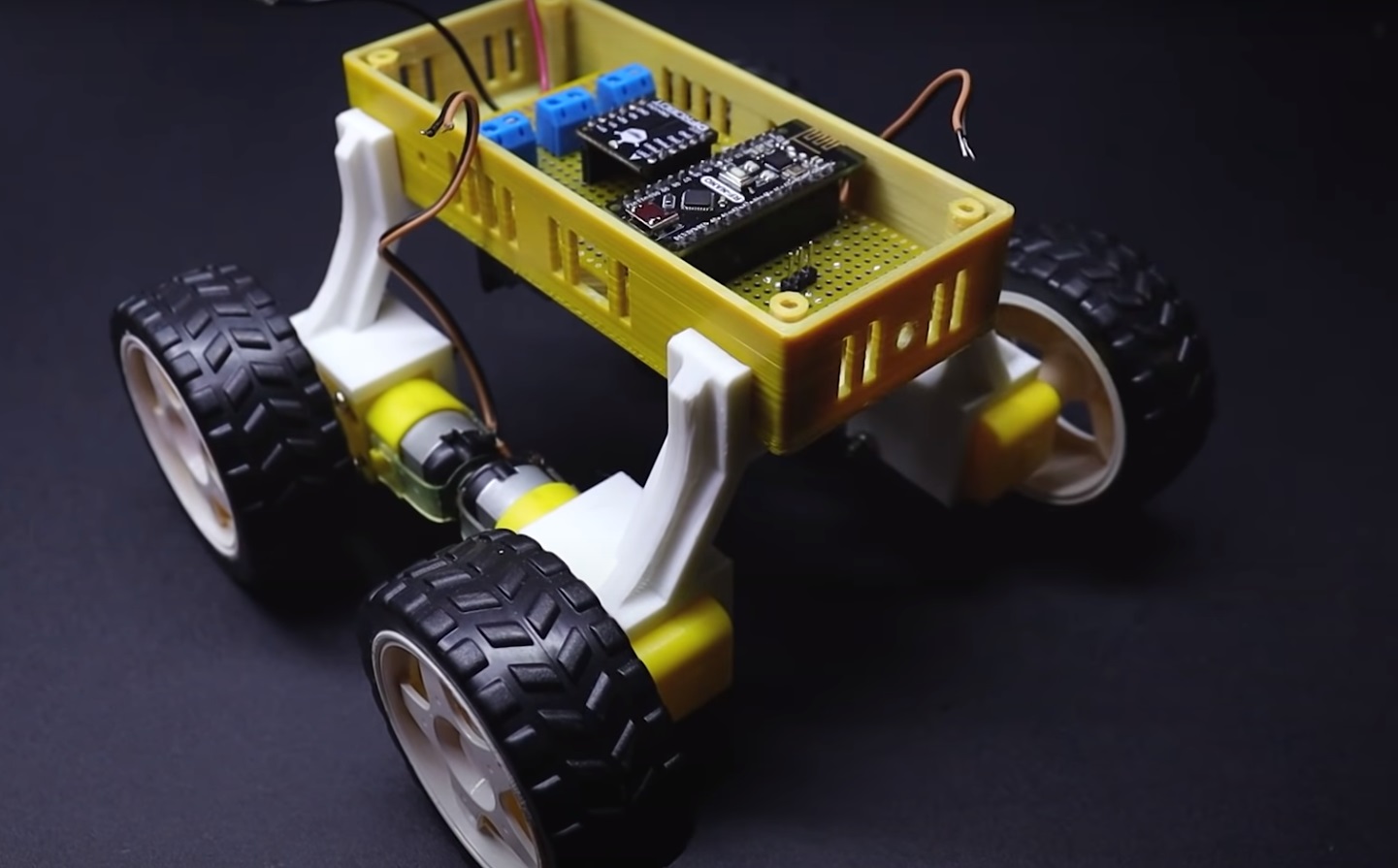
The TT gear motors should then be fastened to the appropriate 3D-printed component mounts. All four, plus two mirror image 3D mounts, will be used.

Attach the main box base to the TT gears and mounts.

Take the rubber wheels and attach them to the TT gears next.

The motors should then be wired as the video instructs. Once that phase is over, turn the robot over.
The battery holder should now be mounted in the robot chassis’s middle.

Now that most of the mechanical components have been resolved, it is time to focus on the micro-electrical gadgets.
The circuit diagrams are shown below.

Build the PCB using the necessary components and the parts illustrated. After that, attach the DC Motor Driver and Arduino RF Nano to the board.
Put the finished PCB board inside the robot’s belly as demonstrated in the movie. Wire up as indicated after that.
Take the metal detector module next. Solder and connect the wires as directed. Glue the positioning arm and the appropriate 3D printed mounting for the metal detector module.
According to the illustration, attach the full metal detecting assembly to the front of the main robot assembly.

Connect the wires to the previously finished PCB. The Arduino RF Nano is now ready for the code upload.
Since the code is somewhat lengthy, we have added a section at the conclusion of this instruction manual. Two sets of code exist, one for the robot and the other for the remote control.
Make sure the Arduino on the robot is loaded with the RX code. For further information, view the video. Place the lid now on top of the robot, and we’ll be halfway done (more or less).
The robot is ready when two batteries are inserted into the battery holder.
The construction of the remote control can now begin. Take the LCD display and attach it on the remote control’s front face.

Now take the joystick modules and attach them to the remote controller’s back plate. Install using a screw.

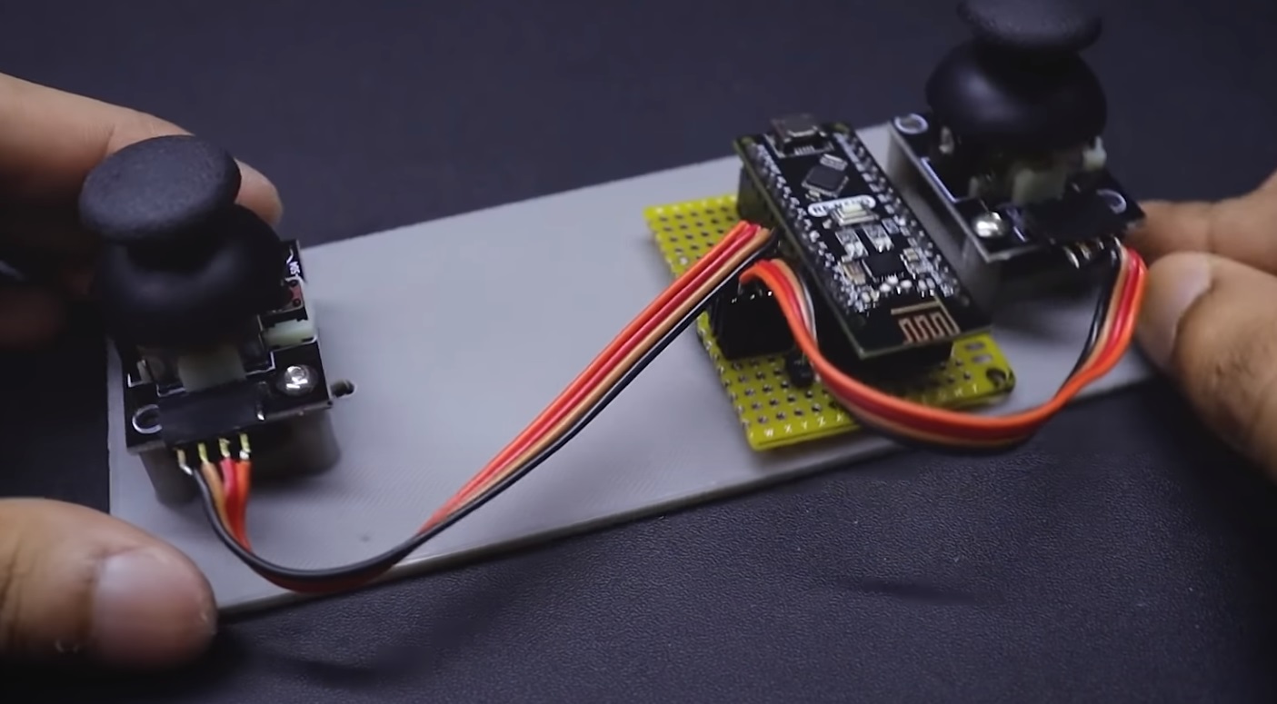
The primary PCB for the remote control must now be constructed. The circuit schematic is shown here.

Assemble as directed, soldering parts into position as necessary. Install the second Arduino RF board in its proper location on the PCB, and then attach it to the rear plate of the 3D-printed remote controller component.

As seen in the video, connect the joysticks to the PCB.
The second battery holder should then be attached to the remote control’s back plate. Connect the wires to the main remote PCB as shown by passing the wires through.
Connect the LCD display to the main remote PCB at this point.

Now upload the second.ino file to the Arduino board for the remote control. This should only contain the TX file. The complete code is included at the conclusion of this instruction manual.
Make care to install the necessary libraries as well.
After that is finished, put the remote control together completely.

This stage is finished by inserting the second set of batteries into the remote control.
Now that the robot and remote control are operational, you are free to conduct as many metal-hunting expeditions as you choose.

Here is the code you need, as promised. Make clean backups of the code before modifying it if you plan to
(or redownload, of course).
Code for the metal detector (download from here or save as Metal Detector RX.ino)
| //Arduino Metal Detector Robot //Receiver Sktech //Created by DIY Builder // Contact me https://www.instagram.com/diy.builder/ // Before uploading the sketch you have to install the required libraries // First go to sketch section >> include library >> manage libaries >> Search RF24 and LiquidCrystal >> Install it >> Done #include #include #include #define sensor A7 int PWM1 = 6; int DIR1 = 7; int PWM2 = 5; int DIR2 = 4; int sensorValue = 0; unsigned long lastReceiveTime = 0; unsigned long currentTime = 0; RF24 radio(10,9); const byte address[6] = “00001”; const byte address1[6] = “00003”; struct Data_Package { byte x1Value; byte y1Value; byte x2Value; byte y2Value; byte sValue; }; Data_Package data; void setup() { Serial.begin(9600); pinMode(DIR1, OUTPUT); pinMode(DIR2, OUTPUT); pinMode(sensor, INPUT); radio.begin(); radio.openReadingPipe(1,address); radio.openWritingPipe(address1); radio.setPALevel(RF24_PA_HIGH); resetData(); } void loop() { radio.startListening(); if(radio.available()) { radio.read(&data, sizeof(Data_Package)); lastReceiveTime = millis(); } currentTime = millis(); if(currentTime – lastReceiveTime > 1000) { resetData(); } Serial.print(“j1PotX: “); Serial.println(data.x1Value); Serial.print(“j1PotY: “); Serial.println(data.y1Value); if(data.y1Value > 200 ) { analogWrite(PWM1, 100); analogWrite(PWM2, 100); digitalWrite(DIR1, HIGH); digitalWrite(DIR2, HIGH); }else if(data.y1Value < 100) { analogWrite(PWM1, 100); analogWrite(PWM2, 100); digitalWrite(DIR1, LOW); digitalWrite(DIR2, LOW); } else if(data.x1Value > 200 ) { analogWrite(PWM1, 100); analogWrite(PWM2, 100); digitalWrite(DIR1, LOW); digitalWrite(DIR2, HIGH); }else if(data.x1Value < 100 ) { analogWrite(PWM1, 100); analogWrite(PWM2, 100); digitalWrite(DIR1, HIGH); digitalWrite(DIR2, LOW); }else if(data.y2Value > 200) { analogWrite(PWM1, 255); analogWrite(PWM2, 255); digitalWrite(DIR1, HIGH); digitalWrite(DIR2, HIGH); }else if(data.y2Value < 100) { analogWrite(PWM1, 255); analogWrite(PWM2, 255); digitalWrite(DIR1, LOW); digitalWrite(DIR2, LOW); }else if(data.x2Value > 200) { analogWrite(PWM1, 255); analogWrite(PWM2, 255); digitalWrite(DIR1, LOW); digitalWrite(DIR2, HIGH); }else if(data.x2Value < 100) { analogWrite(PWM1, 255); analogWrite(PWM2, 255); digitalWrite(DIR1, HIGH); digitalWrite(DIR2, LOW); } else { analogWrite(PWM1, 0); analogWrite(PWM2, 0); } delay(5); radio.stopListening(); sensorValue = analogRead(sensor); data.sValue = sensorValue; Serial.print(“sensor”); Serial.println(sensorValue); radio.write(&data, sizeof(Data_Package)); delay(5); } void resetData() { data.x1Value = 127; data.y1Value = 127; data.x2Value = 127; data.y2Value = 127; data.sValue = 0; } |
Code for the metal detector (save and upload as Metal_Detector_TX.ino or download from here).
| //Arduino Metal Detecting Robot // Transmitter Sketch // Created by DIY Builder // Contact me https://www.instagram.com/diy.builder/ // Before uploading the sketch you have to install the required libraries // First go to sketch section >> include library >> manage libaries >> Search RF24 and LiquidCrystal >> Install it >> Done #include #include #include #include #include LiquidCrystal_I2C lcd(0x3F, 20, 4); RF24 radio(10,9); const byte address[6] = “00001”; const byte address1[6] = “00003”; struct Data_Package { byte x1Value; byte y1Value; byte x2Value; byte y2Value; byte sValue; }; Data_Package data; void setup() { Serial.begin(9600); lcd.init(); lcd.backlight(); radio.begin(); radio.openWritingPipe(address); radio.openReadingPipe(1, address1); radio.setPALevel (RF24_PA_HIGH); } void loop() { delay(5); radio.stopListening(); Serial.print(“x1Value”); Serial.println(data.x1Value); Serial.print(“y1Value”); Serial.println(data.y1Value); Serial.print(“x2Value”); Serial.print(data.x2Value); Serial.print(“y2Value”); Serial.print(data.y2Value); data.y1Value = map(analogRead(A0), 0, 1023, 0, 255); data.x1Value = map(analogRead(A1), 0, 1023, 0, 255); data.y2Value = map(analogRead(A2), 0, 1023, 0, 255); data.x2Value = map(analogRead(A3), 0, 1023, 0, 255); radio.write(&data, sizeof(Data_Package)); delay(5); radio.startListening(); if(radio.available()) { radio.read(&data, sizeof(Data_Package)); int sensor = data.sValue; Serial.print(“button”); Serial.println(sensor); lcd.setCursor(0,0); lcd.print(“Robot Connected”); if(sensor < 200){ lcd.setCursor(0,1); lcd.print(“Metal Searching “); }else { lcd.setCursor(0,1); lcd.print(” Metal Found “); } }else { lcd.setCursor(0,0); lcd.print(” Hello World! “); lcd.setCursor(0,1); lcd.print(“Robot Disconnected”); } } |
Hope you find this project simple. Superkitz will be back soon with more informative blogs. Thank You Bye.

