A solar tracker is a tool that directs a payload in the direction of the Sun. Typically, payloads consist of solar cells, parabolic troughs, fresnel reflectors, lenses, or heliostat mirrors.
Solar panels function most effectively when they are pointed directly at the sun. This seems straightforward enough, however the sun travels during the day. In order to orient your panel or array of panels directly towards the sun, there are now a variety of systems known as solar trackers that operate on a variety of principles.
Let’s create a solar tracker with two servo motors, an Arduino UNO board, and a light sensor made of four LDRs.
Components Required
- Arduino UNO
- SG90 Micro-servo motor
- Light Sensors
- LDR, 5 Mohm
- Resistor 330 ohm
- Rotary potentiometer (generic)
- Pushbutton Switch, Pushbutton
- Mini Solar Panel
Other Tools
- Arduino IDE
- Parallax PLX-DAQ
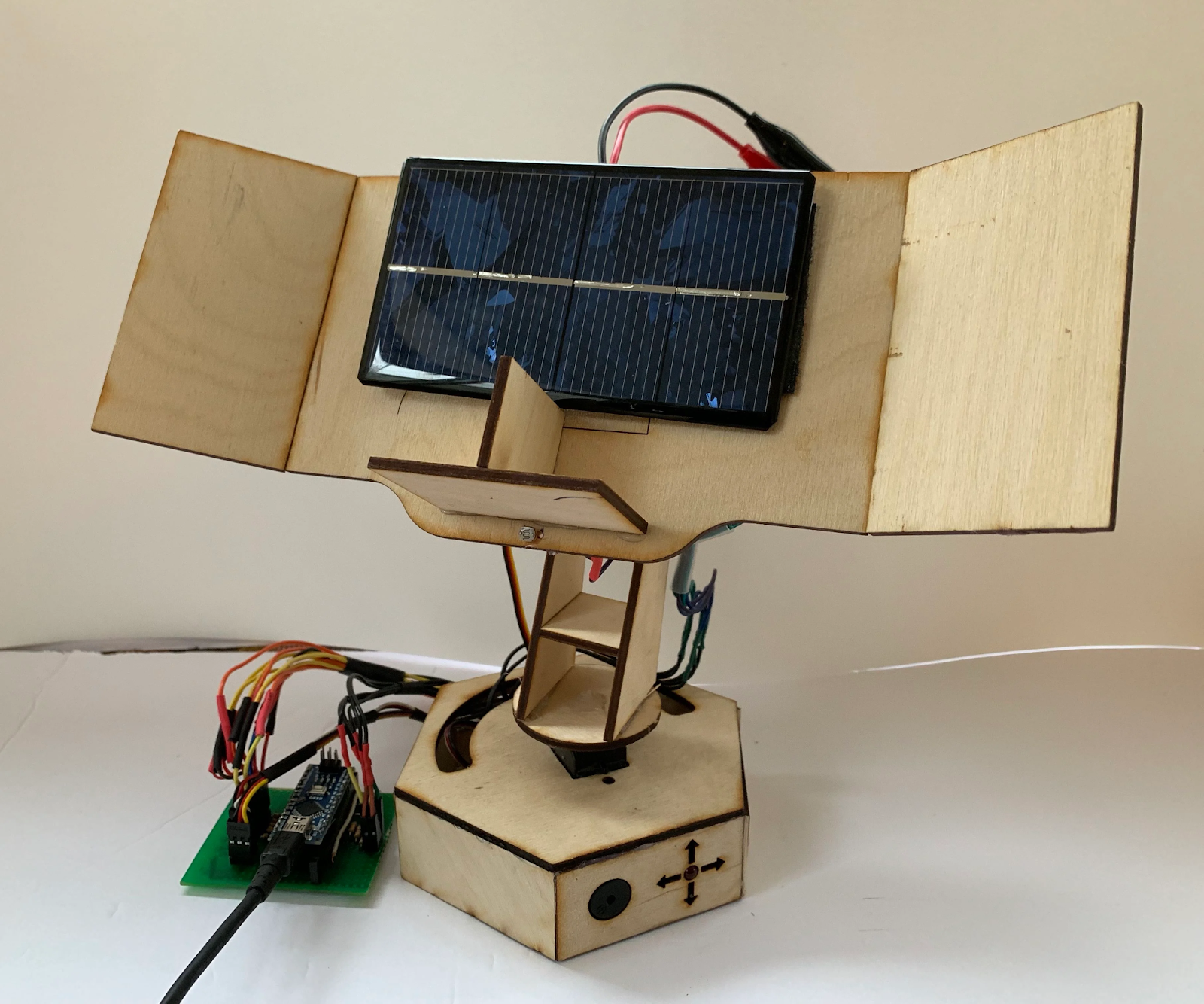
Proposed System
The suggested prototype is built on a dual-axis solar tracker that is managed by an Arduino Uno, an open-source prototyping platform with user-friendly hardware and software. Light-dependent resistor (LDR) sensors can be used to automatically control the solar tracker, or a potentiometer can be used to manually control it. Additionally, this test bench offers Excel-based virtual instrumentation that allows users to collect and display data from their solar trackers. The hardware used has been selected to be reasonably priced, small, and adaptable. The intended test bench is made to assist students in better grasping control theory and its applications.

It is built on a solar tracker that rotates either automatically using a potentiometer and four LDR sensors or manually using two servomotors (SM1 and SM2). A push-button is utilized to alternate between the two modes, automated and manual.
To regulate the movement of the SM1 (up-down servomotor) or SM2 (left-right servomotor), a second push-button is utilized to connect them to the potentiometer. Additionally, a computer is utilized as a virtual instrument to display the PV panel’s mode, current, voltage, and power over time in MS Excel. To implement all of the system’s software requirements, an Arduino Uno board is used.
Circuit Diagram

Working
The circuitry for the LDR sensor is intended to function as a voltage divider. The divider output voltage varies in direct proportion to the variation in light intensity. The output of the voltage divider is linked to an analog input (such as A0) of the microcontroller. The top of the potential divider is set at 5 V, the ground is at 0 V. It is, therefore, able to determine the intensity of light thanks to the microcontroller’s Analog to Digital Converter (ADC), which transforms the analog value read by A0 into a digital number between 0 and 1023 because the ADC is coded in 10 bits. Resistors used in voltage dividers have a value of 330.

There are two 180-degree servomotors in use. a left-right servomotor (MG996R) that controls the sun tracker in accordance with its vertical axis. Additionally, a micro servo motor (SG90), which is an up-down servomotor, is used to operate the solar tracker in accordance with the horizontal axis.
The benefit of the servomotor is that we don’t need any drivers because we can regulate its stop, run, rotational direction, and speed using a single low current wire connected directly to the output of the microcontroller. According to Fig. 3, a 3-wire electrical cable with two wires for supply and one wire for PWM to regulate its positions is utilized to control the employed servo motors by the Arduino UNO board.
Setup Procedure
Step-1
- Take cardboard. To accommodate the LDR, create a hole in the centre and four holes on each side.
- Attach the solar panel to the cardboard by sticking it there, then extend the panel’s two wires as shown.

Step 2
- Now, shorten one of the LDR’s two leads so that the other lead is longer.
- Place these four LDRs in the four indicated holes.
- As seen below, bend the straight perforated metal strip.
- Put the bent metal strip to the cardboard’s backside.
- To firmly fix the LDR, apply glue to them.

Step 3
- Solder the LDR’s two leads as shown.
- 10k ohm resistors should be soldered to the LDR’s other ends.
- Connect a wire to the four leads of the four LDRs to join them.

Step 4
- Take a bus wire now.
- Four LDRs’ outputs are connected to an Arduino board like this.
- As depicted in the picture, insert it into the metal strip.
- The four wires should now be soldered to the four LDRs at any position between the LDR and the resistor.

Step 5
- Another two-wire bus should be inserted as illustrated into the perforated metal strip.
- This is used to power the LDR circuit with Vcc and GND.
- To the leads of LDRs that are connected to resistors, solder one wire, and to the other leads, solder the other wire.
- Using a wire in the manner illustrated, short the leads of any LDRs attached to resistors.

Step 6
- Now use a screw to attach a servo motor to the perforated metal strip.
- To firmly fix the servo, use glue.

Step 7
- Take another piece of perforated metal that is straight and bend it as shown in the illustration.

Step 8
- Now attach the solar panel setup and first servo motor to the second servo motor’s metal strip as illustrated.

Project Code
| #include <Servo.h> | |
| //defining Servos | |
| Servo servohori; | |
| int servoh = 0; | |
| int servohLimitHigh = 160; | |
| int servohLimitLow = 20; | |
| Servo servoverti; | |
| int servov = 0; | |
| int servovLimitHigh = 160; | |
| int servovLimitLow = 20; | |
| //Assigning LDRs | |
| int ldrtopl = 2; //top left LDR green | |
| int ldrtopr = 1; //top right LDR yellow | |
| int ldrbotl = 3; // bottom left LDR blue | |
| int ldrbotr = 0; // bottom right LDR orange | |
| void setup () | |
| { | |
| servohori.attach(10); | |
| servohori.write(0); | |
| servoverti.attach(9); | |
| servoverti.write(0); | |
| delay(500); | |
| } | |
| void loop() | |
| { | |
| servoh = servohori.read(); | |
| servov = servoverti.read(); | |
| //capturing analog values of each LDR | |
| int topl = analogRead(ldrtopl); | |
| int topr = analogRead(ldrtopr); | |
| int botl = analogRead(ldrbotl); | |
| int botr = analogRead(ldrbotr); | |
| // calculating average | |
| int avgtop = (topl + topr) / 2; //average of top LDRs | |
| int avgbot = (botl + botr) / 2; //average of bottom LDRs | |
| int avgleft = (topl + botl) / 2; //average of left LDRs | |
| int avgright = (topr + botr) / 2; //average of right LDRs | |
| if (avgtop < avgbot) | |
| { | |
| servoverti.write(servov +1); | |
| if (servov > servovLimitHigh) | |
| { | |
| servov = servovLimitHigh; | |
| } | |
| delay(10); | |
| } | |
| else if (avgbot < avgtop) | |
| { | |
| servoverti.write(servov -1); | |
| if (servov < servovLimitLow) | |
| { | |
| servov = servovLimitLow; | |
| } | |
| delay(10); | |
| } | |
| else | |
| { | |
| servoverti.write(servov); | |
| } | |
| if (avgleft > avgright) | |
| { | |
| servohori.write(servoh +1); | |
| if (servoh > servohLimitHigh) | |
| { | |
| servoh = servohLimitHigh; | |
| } | |
| delay(10); | |
| } | |
| else if (avgright > avgleft) | |
| { | |
| servohori.write(servoh -1); | |
| if (servoh < servohLimitLow) | |
| { | |
| servoh = servohLimitLow; | |
| } | |
| delay(10); | |
| } | |
| else | |
| { | |
| servohori.write(servoh); | |
| } | |
| delay(50); | |
| } |
Hope You all Like this simple Arduino Solar Tracker project. Superkitz will be back soon with more interesting blogs, Thank You
